Appearance
Timber member design (AS 1720.1)
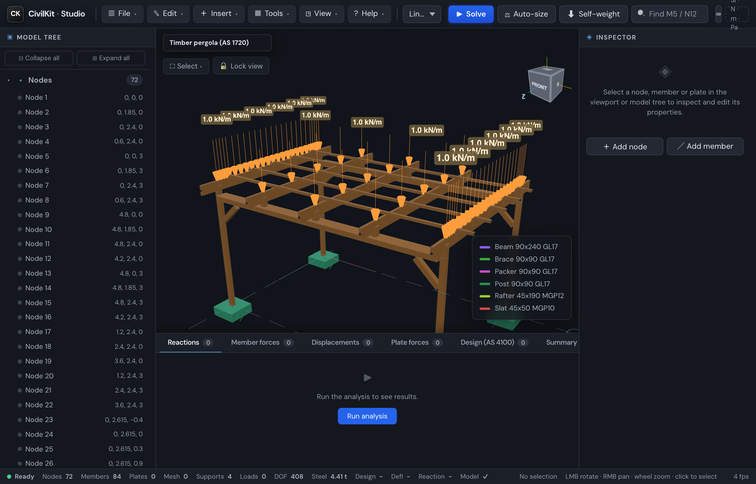
CivilKit Studio can design timber beams, posts and rafters to AS 1720.1 (the Australian timber structures standard) - the same model you analyse for steel can carry timber members, checked automatically when you solve.
Cross-checked, not yet verified against the standard
The timber check reproduces an independent open-source implementation of AS 1720.1 (timberas, University of Queensland) over 1,100 cases and the worked examples of the SA HB 108 Timber Design Handbook. It has not yet been checked against the pages of AS 1720.1 itself. Read Scope & assumptions at the bottom before relying on a number. Timber connections are not designed (the connection tools are steel-only for now), and combined bending-plus-compression is not checked yet.
A "member" is one stick of timber in the model (a beam, post or rafter). A "section" is its size and grade - e.g. 240x45 MGP10, meaning 240 mm deep, 45 mm wide, machine-graded pine grade 10.
Assigning a timber section
Timber lives in its own catalogue, separate from steel, in the same section picker.
- Select a member and open its inspector (the panel on the right).
- Click Browse sections to open the section library.
- At the top, change the Catalogue dropdown from a steel country to Timber (AU, AS 1720). The title switches to Timber section library.
- Pick a size from the list (e.g. 190x45 F17) and apply it.
Choosing a timber section does three things automatically:
- Routes the member to AS 1720 - it will be checked to the timber standard, not AS 4100 steel.
- Sets timber stiffness - the member is pointed at a timber material whose stiffness (
E, the modulus of elasticity) comes from the grade, so the analysis bends it like wood, not steel. Timber is far less stiff than steel, so deflections will be larger and realistic. - Renders it in a wood tone - the member is drawn in a timber colour in the 3D view, so you can see at a glance which members are timber.
The grade is part of the name
A timber section name carries both the size and the stress grade - the strength class. The library covers visually/machine-stress-graded sawn timber (F5, F7, F8, F11, F14, F17, F22, F27 and MGP10, MGP12, MGP15) and glue-laminated timber (GL8, GL10, GL12, GL13, GL17). Higher numbers are stronger and stiffer. The design check's grade list also offers F4, F34 and GL18.
Seeing the design check
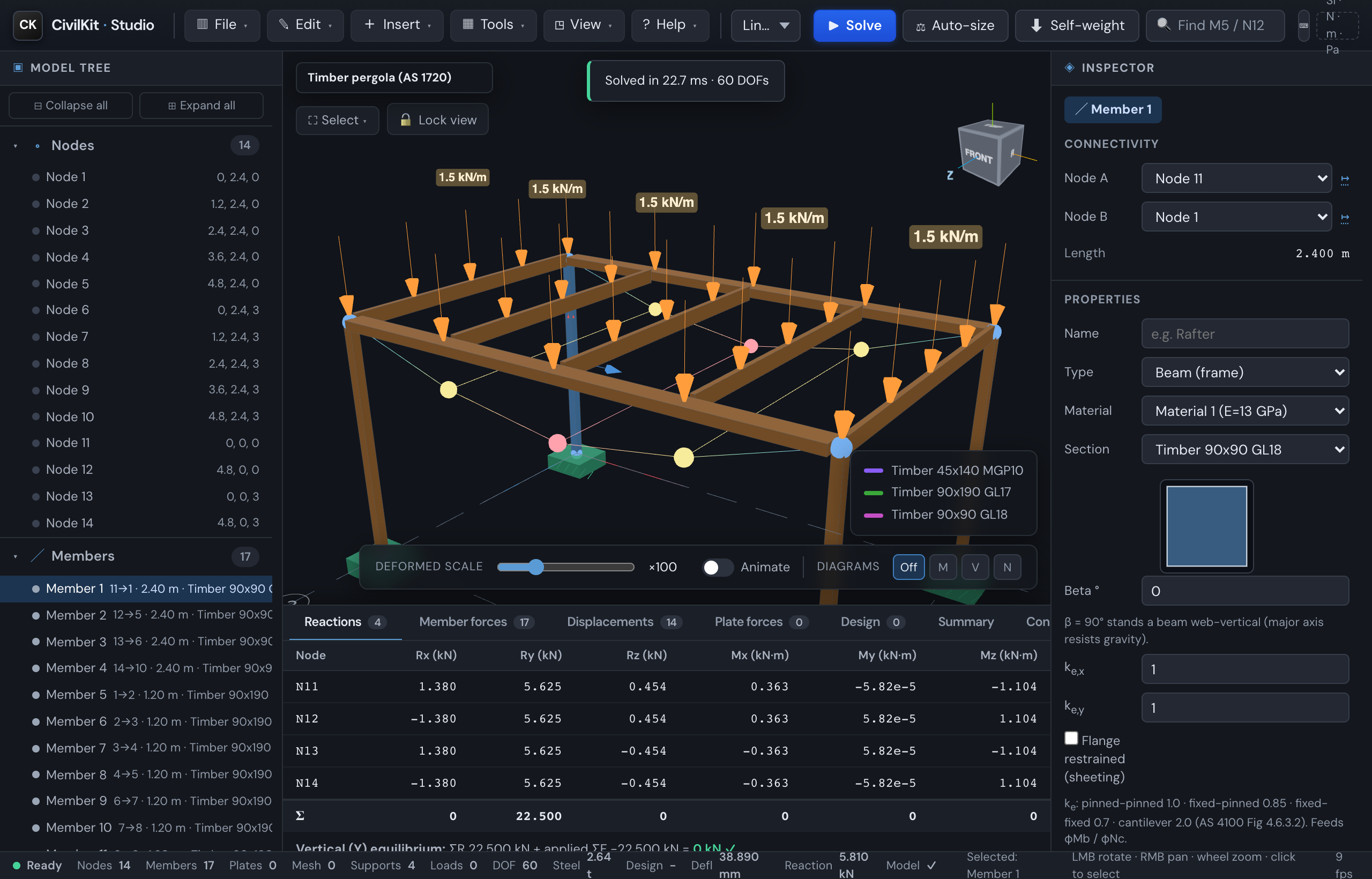
The check appears in the inspector after you solve.
- Assign a timber section (above).
- Solve the model (press
S) with Linear static or P-Delta. - Select the timber member. Its Timber member (AS 1720.1) panel sits in the inspector's Connection & material checks group. For a timber member that group opens automatically and the timber panel leads it, so the check is in front of you the moment you select the member - no hunting through folds.
The demands (the forces the member must carry - bending, compression and shear) are pulled straight from the analysis, so you don't type them in. They refresh each time you re-solve.
Inputs and outputs
The panel shows what it used and what it found.
| Field | What it is |
|---|---|
| Grade | The stress grade (F4...F34, MGP10...15, GL8...GL18). Set by the section, editable here. |
| Species | Softwood or hardwood. It changes an F-grade's tension strength. |
| Seasoning | Seasoned or unseasoned. It changes the stability constants ρb and ρc. |
| Category | The application category of Table 2.1, which sets the capacity factor φ: 1 for secondary members and houses, 2 for primary members (the default), 3 for post-disaster structures. |
| Breadth b (mm) | Section width. |
| Depth d (mm) | Section depth (the tall direction). |
| Length L (mm) | The member length. The inspector fills it from the model. It is the column length for buckling, and the span for load sharing. |
| g13 | The effective length factor for column buckling (Table 3.2): 1.0 pinned-pinned, 0.7 fixed-fixed, 0.9 for wall studs, and so on. |
| Restraint spacing Lay (mm) | The spacing of restraints that stop the member moving sideways (noggings, purlins, flooring). 0 means the full length, which is the conservative case. |
| Restrained edge | Whether those restraints hold the compression edge or the tension edge of a beam. |
| k1 (duration) | Load-duration factor (Table 2.3): 1.0 for wind (5 seconds), 0.94 for 5 days, 0.8 for 5 months, 0.57 for permanent load. The tooltip lists them. |
| M* (kN·m) | Design bending moment from the analysis (the bending demand). |
| N*c (kN) | Design compression force from the analysis. |
| V* (kN) | Design shear force from the analysis. |
The k-factors are AS 1720.1 modification factors: multipliers that adjust the raw timber strength for the real service conditions. Only k1 (load duration) is typed in, because it depends on the load case. The rest are worked out from the inputs above and shown in the result: k4 (moisture), k6 (temperature), k9 (strength sharing), and k12, the stability factor. k12 is calculated separately for bending (lateral buckling, from the restraint spacing and edge) and for compression (column buckling about each axis, from L, g13 and the restraint spacing).
What the panel reports:
| Output | Meaning |
|---|---|
| Bending M*/φM | Bending utilisation - demand ÷ capacity (a bar; green ≤ 1, red > 1). |
| Compression N*/φNc | Compression utilisation, against the weaker buckling axis. |
| Shear V*/φV | Shear utilisation. |
| Governing | The worst of the three ratios, with OK (≤ 1) or OVER (> 1) and which action drives it. |
| φM / φNc / φV | The design capacities (kN·m / kN / kN) - bending, compression, shear. |
| φ, k-factors | The capacity factor and the k4, k6, k9 and k12 the check used. |
| Stability | Shown only when there is no member length: the stability check was then not made. |
"Utilisation" is demand divided by capacity: under 1.0 the member is adequate, over 1.0 it is overloaded. "φ" (phi) is the capacity-reduction factor already built into the capacity, as the standard requires.
Show your working
The panel includes a clause-referenced AS 1720.1 working that substitutes your k-factors and the slenderness coefficients (S1, S3, S4) into the capacity formulas, with a Copy button - so you can paste the calculation, with the standard's clauses, into your own notes. The capacities come from the AS 1720.1 calculation core (the same engine behind the calculators).
Try the timber pergola sample
The quickest way to see it working is the built-in sample.
- Open the model gallery and load Timber pergola (AS 1720) (under Frames).
- It is a 4.8 x 3.0 m, 2.4 m-high timber frame: glulam posts (90x90), glulam eave beams (90x190) and MGP10 rafters (45x140) under a light roof load. The whole frame renders in the timber tone.
- Solve (
S), then select any member - posts, beams or rafters - to see its AS 1720.1 check populated with the real forces from the analysis.
There is also a simpler Timber floor beam (AS 1720) sample (under Beams): a 4.5 m simply-supported F17 hardwood floor beam (65x300) under a floor load - good for seeing a single bending-governed member.
Scope & assumptions (read before professional use)
Be aware of these limits:
Cross-checked, not verified. The characteristic strengths (Tables H2.1 and H3.1, and AS/NZS 1328.1 for glulam), φ, k4, k6, k9 and k12 agree with an independent implementation and with the SA HB 108 worked examples. They have not yet been read off the pages of AS 1720.1. The row-by-row status is kept in the project's AS 1720 verification ledger.
Section library not yet verified. The timber catalogue is flagged
verified: false- the geometry is exact (computed from breadth x depth) but the grades and stiffness values are pending an engineer cross-check against the standard and manufacturer data. Confirm grade and properties before relying on a result.Density is nominal - a softwood/hardwood default is used for self-weight only, not a graded value.
Stability follows the restraint you describe. k12 is worked out from the member length, g13, the restraint spacing and the restrained edge. Until you set them, a member is treated as unrestrained over its full length, which is the conservative case. If you describe restraint that isn't really there (noggings, fixings, a floor), the capacity will be unconservative.
Load duration is yours to set. k1 defaults to 1.0 (a short-term load such as wind). For permanent or long-term load cases, set it from Table 2.3.
Connections are not designed. Timber joints (bolts, coach screws, nail plates, joist hangers) are not checked - the connection designer is steel-only at present. Design timber connections separately.
Not yet checked: combined bending plus compression or tension (Cl 3.5, 3.6), bearing (with k7), LVL and A-grade material.
Verify before professional use
Always confirm the grade, section properties, k-factors and the governing load case against AS 1720.1 and a manufacturer's data before relying on these numbers. For the underlying maths and other materials, see the design checks overview, sections and the concrete member design page.