Appearance
Design checks (AS 4100)
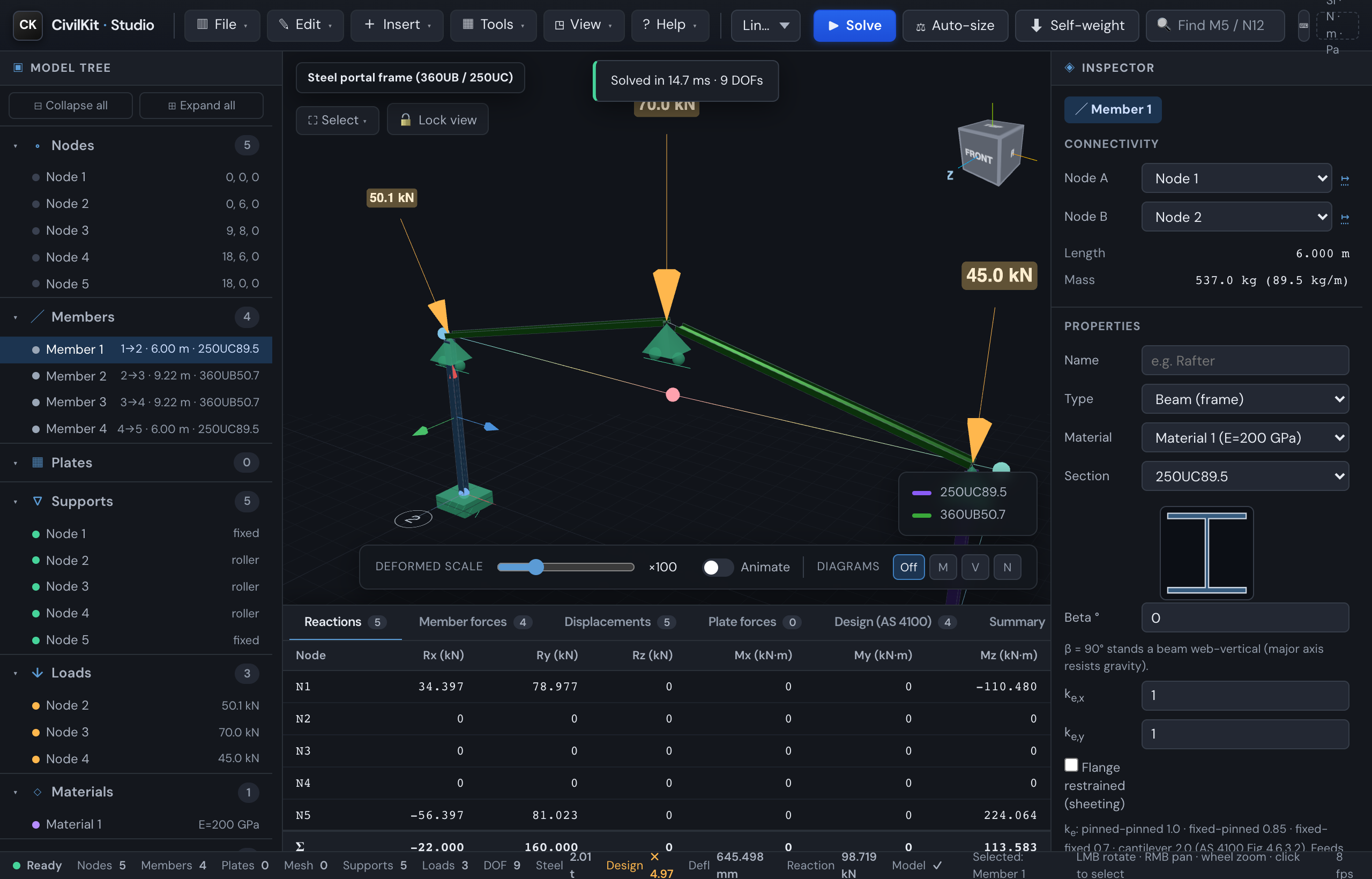
CivilKit Studio computes AS 4100 steel member capacities automatically when you solve, and reports per-member utilisation - turning the analysis into a design tool.
How to get a design check
- Assign a real section. Open a member's inspector → Browse sections and pick a catalogue section (the check needs section geometry - depth, flange, web, Zx/Sx - that the catalogue carries). The gallery's "real section" models already have these.
- Solve (
S) with Linear static or P-Delta. - Read the results in the Design (AS 4100) tab of the results panel, or select a member to see its check in the inspector ("Result · AS 4100 design").
What's reported
| Column | Meaning |
|---|---|
| Class | Section compactness - compact / non-compact / slender (Cl 5.2) |
| φMsx | Design section moment capacity (Cl 5.2), kN·m |
| φMbx | Design member moment capacity - lateral-torsional buckling (Cl 5.6), kN·m |
| M*x | Design bending moment from the analysis (max over the member), kN·m |
| φNc | Design member compression capacity (Cl 6.3), governing axis, kN |
| N*c | Design compression from the analysis, kN |
| Utilisation | Governing demand/capacity ratio |
| Status | OK (≤ 1) or OVER (> 1) |
Utilisation is the worst of the bending (M*/φMb) and compression (N*/φNc) ratios.
What governs each ratio
Hover a utilisation cell to see what drives it, e.g. "0.77 - governed by combined M-N (Cl 8.3/8.4)" or "...governed by shear V*/φVv" - so you can read the design table without opening each member's inspector.
Working the design table
The Design (AS 4100) tab has a few controls for working through a real model:
- Failures only - filter the table to members failing the check (utilisation
1), so you fix the red ones first.
- Group by section - engineers design to the worst member of each section (a "design member"), not member by member. This toggle collapses the per-member table to one row per distinct section, showing the section name, the member count, and the governing (worst) member with its utilisation and status. Click a row to select that governing member. Toggle off to return to the full per-member table. It also carries the steel mass per section group (kg / t), which drives cost and take-off.
- Gov. case - with load combinations, this column shows which Σ combination governs each member's utilisation, so you can see the driving case at a glance.
Serviceability
Alongside strength, the panel reports a serviceability deflection check: the worst-member span / deflection ratio against a configurable limit, stated with a verdict, e.g. "L/δ = 1/108 vs L/250 ✗" (✓ when within limit). The pass test uses the unrounded ratio so a borderline case is not masked by rounding.
The limit is set in Settings → Deflection limit (SLS) - L/180, L/250 (default), L/300 or L/360 - to suit the member and finish (e.g. L/180 for cantilevers, L/360 for brittle finishes). The chosen limit applies live in the design panel and the PDF report, which always agree, and persists across a refresh.
International steel (AISC 360 / Eurocode 3)
The same model can be checked to the US and European steel codes, not just AS 4100. Select a steel member and open International steel check (AISC 360 / EC3) in the inspector's Connection & material checks group, then pick the code:
- AISC 360 (LRFD) - φPn, φMnx, φMny (with lateral-torsional buckling), φVn and the Chapter H combined-actions check (H1-1b).
- Eurocode 3 - Nc,Rd, My,Rd, Mb,Rd (LTB), Vpl,Rd and the Cl 6.3.3 interaction.
Section properties and the demands (N*, M*x, M*y, V*) are taken from the analysis; the effective length Le defaults to the member length and is editable. The panel shows the per-action ratios, a combined utilisation with the governing equation, the capacities and the section class. These capacities are validated through the solver's WASM boundary against first principles. As with AS 4100, treat it as a first-pass check and verify restraints and detailing.
Choosing your code region
So you don't have to pick the code member-by-member, set the design region once and the checks follow it:
- Global default - Settings → Design region (Australia/NZ, United States, Europe, United Kingdom, Canada, Thailand). Persists across sessions.
- Per-project override - the Design region field in the report title block. It rides on the model, so the same job designs to the same code on any machine, for any colleague (export / import / autosave all carry it).
- Resolution: project override → global default → Australia.
When the region's steel code is international (US/Canada → AISC 360, Europe/UK → Eurocode 3), the International steel check defaults to that code, opens, and leads the other checks; AU/NZ keep AS 4100 first. The region also points the section library at that country's catalogue by default, so a US job opens on US sections. Changing the panel's code or the picker's country by hand always wins.
Scope & assumptions (read before professional use)
This is an early, transparent slice - the capacities are validated against the ASI/OneSteel Design Capacity Tables (see AS 4100 API), but the member-design inputs use simplifying assumptions, shown in the panel footnote:
- Steel grade: AS/NZS 3679.1 Grade 300, with
fyby flange thickness (320 / 300 / 280 MPa for ≤11 / ≤17 / >17 mm). - Effective length
Le = the member's length- no intermediate restraints are modelled. If your member is restrained between ends, φMb / φNc are conservative; a restraint editor is planned. - αm = 1.0 (uniform-moment, conservative) for φMb.
- φNc uses
r = √(I/A)per axis (minor axis usually governs). - Combined actions (Cl 8.3/8.4) are applied - the reported Utilisation is the M-N interaction, evaluated on both axes (major φMbx and minor φMby), and the worse axis governs. φNt (tension) and φVv (shear) are also shown.
- Biaxial note: the per-axis combined checks each use the full axial force; the full Cl 8.4.5 biaxial interaction (combined Mx+My in one inequality) is a planned refinement, so for members with large moments about both axes the utilisation is slightly non-conservative versus that interaction.
Verify before professional use
Always confirm restraints, section data, steel grade and the governing load combination against the standard and a manufacturer catalogue before relying on these numbers.