Appearance
Design calculators
The Tools menu holds thirteen standalone calculators - quick, single-element checks you can run without building a full model. Type a few numbers and the answer updates live, so they're handy for sizing a beam, a footing or a bolt before (or instead of) drawing anything.
Every calculator opens as a small dialog: inputs on the left, results on the right that recompute as you type. Most show a green OK / red OVER verdict with a utilisation number (demand ÷ capacity - under 1.00 passes, over 1.00 fails) and name the governing (worst) check at the top. A ⧉ Copy button puts the inputs and results on your clipboard as a tab-separated table you can paste into a spreadsheet or email.
Send a result into the report
The footing, site-classification, retaining-wall and wind calculators also have a + Add to report button. It drops the result into the Design calculations section of the PDF report as a titled card, so a standalone check reaches the submitted package without re-typing. Unverified calculators carry a caution on the card and trip the report's PRELIMINARY banner until you sign them off.
First-pass tools - verify before professional use
These are transparent first-pass design aids built on simplified assumptions (noted in each dialog's footnote). Always confirm the result against the relevant Standard, a manufacturer catalogue and - for anything in the ground - the soil report before relying on it. The concrete and geotechnical calculators in particular skip detailing, load combinations and many real-world effects.
Section calculator
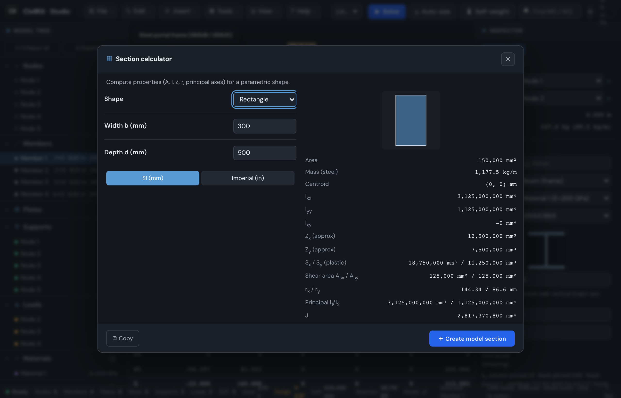
Works out the geometric properties (area, second moments of area, section moduli, radius of gyration, torsion constant) for a shape you describe by its dimensions - useful when a member isn't a standard catalogue size. See also the section library for ready-made catalogue sections.
- Tools → Section calculator…
- Pick a Shape: Rectangle, Circle, RHS (hollow box), CHS (pipe) or I-section.
- Type the dimensions (in mm) for that shape - the input rows change to match the shape.
- Read the properties on the right; a small outline preview of the shape is drawn above them.
- (Optional) Switch the SI (mm) / Imperial (in) toggle to display the results in either unit system.
- (Optional) ⧉ Copy the table, or + Create model section to add this section to your model.
| Input (by shape) | Meaning |
|---|---|
| Rectangle | Width b, Depth d (mm) |
| Circle | Diameter (mm) |
| RHS (hollow box) | Width b, Depth d, Wall t (mm) |
| CHS (pipe) | Outer diameter, Wall t (mm) |
| I-section | Depth d, Flange width bf, Web tw, Flange tf (mm) |
| Output | Meaning |
|---|---|
| Area | Cross-sectional area |
| Mass (steel) | Self-weight per metre, assuming steel (7850 kg/m³) |
| Centroid | The shape's centre of area |
| Ixx / Iyy / Ixy | Second moments of area (bending stiffness about each axis) |
| Zx / Zy (approx) | Elastic section moduli |
| Sx / Sy (plastic) | Plastic section moduli |
| Shear area Asx / Asy | Effective area resisting shear on each axis |
| rx / ry | Radius of gyration (drives slenderness / buckling) |
| Principal I1 / I2 | Maxima/minima inertia on the principal axes |
| J | Torsion constant (exact for solid rectangle/circle and open I-sections; "approx" for hollow/arbitrary shapes) |
| Iw (warping) | Warping constant - the partner to J for lateral-torsional buckling; non-zero only for open sections |
Create model section
+ Create model section saves the computed shape into your model's section list. If a member is selected when you click it, the new section is assigned to that member straight away; otherwise it's added to the list for you to assign later. The new section carries its area, inertias and self-weight, so design checks can use it.
RC slab calculator
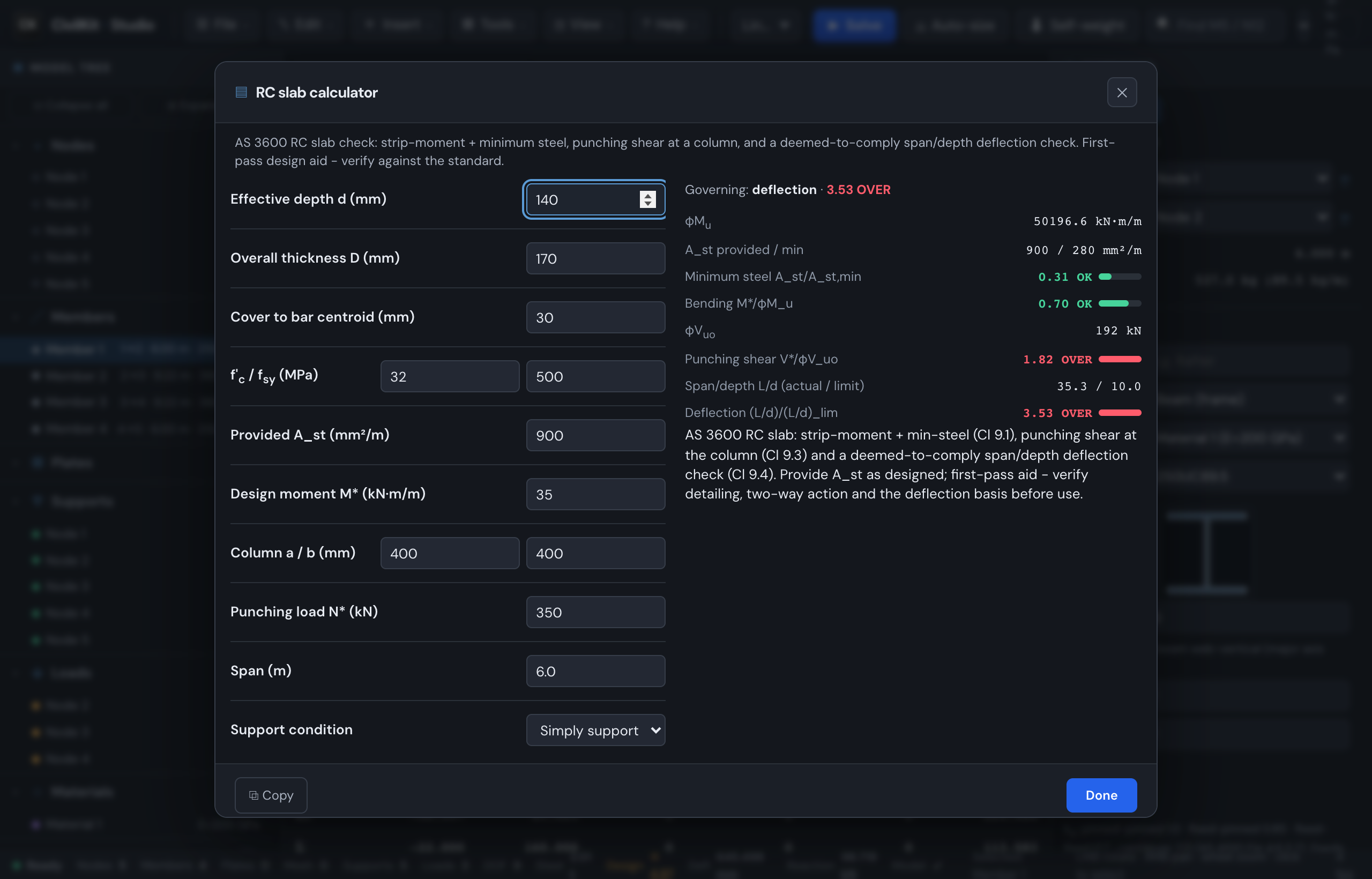
A reinforced-concrete slab check to AS 3600: it verifies bending and minimum steel across a one-metre strip, punching shear where a column lands on the slab, and a span-to-depth deflection rule of thumb. Background on the concrete workflow is in the concrete guide.
- Tools → RC slab calculator…
- Enter the slab geometry, concrete and steel grades, the reinforcement you intend to provide, and the design moment and punching load.
- Choose the Support condition (simply supported, continuous or cantilever) - it sets the allowable span/depth ratio.
- Read the verdict at the top and the per-check rows; ⧉ Copy if needed.
| Input | Meaning |
|---|---|
| Effective depth d (mm) | Depth from the top to the centre of the tension steel |
| Overall thickness D (mm) | Total slab thickness |
| Cover to bar centroid (mm) | Distance from the face to the bar centre |
| f'c / fsy (MPa) | Concrete strength / steel yield strength |
| Provided Ast (mm²/m) | Reinforcement steel area you're providing, per metre width |
| Design moment M (kN·m/m)* | The bending demand per metre |
| Column a / b (mm) | Plan size of the supporting column (for punching) |
| Punching load N (kN)* | The load punching through the slab at the column |
| Span (m) | Slab span (for deflection) |
| Support condition | Simply supported / continuous / cantilever |
| Output | Meaning |
|---|---|
| φMu | Design bending capacity of the strip |
| Ast provided / min | Your steel vs the code minimum |
| Minimum steel | Utilisation - is there enough steel to satisfy the minimum |
| Bending M/φMu* | Bending utilisation |
| φVuo | Punching shear capacity at the column |
| Punching shear V/φVuo* | Punching utilisation |
| Span/depth L/d (actual / limit) | Deflection rule-of-thumb ratio vs its limit |
| Deflection | Deflection utilisation |
Provide the steel as designed
Enter the reinforcement you actually intend to provide in Ast - the calculator checks that amount, it does not size the bars for you. The deflection row is a deemed-to-comply span/depth check, not a calculated deflection.
RC beam calculator
Checks a single rectangular reinforced-concrete beam section to AS 3600 for bending (φMu) and the concrete contribution to shear (φVuc), against the moment and shear you enter.
- Tools → RC beam calculator…
- Enter the beam width and effective depth, the concrete/steel grades, and the tension (and any compression) steel areas.
- Enter the design moment M* and shear V*.
- Read φMu, the ductility flag and the shear capacity on the right.
| Input | Meaning |
|---|---|
| Width b (mm) | Beam width |
| Effective depth d (mm) | Top to centre of the tension steel |
| Compression-steel depth dsc (mm) | Top to the centre of any compression steel |
| f'c / fsy (MPa) | Concrete strength / steel yield strength |
| Tension steel Ast / comp. Asc (mm²) | Bottom (tension) and top (compression) bar areas |
| Design moment M (kN·m)* | Bending demand |
| Design shear V (kN)* | Shear demand |
| Output | Meaning |
|---|---|
| φMu | Design bending capacity |
| ku / φ | Neutral-axis depth ratio and the strength reduction factor; flags over-reinforced (ku > 0.36) when ductility isn't assured |
| Bending M/φMu* | Bending utilisation |
| φVuc | Concrete shear capacity (no stirrups) |
| Tensile steel ratio ρw | Tension reinforcement ratio |
| Shear V/φVuc* | Shear utilisation on the concrete alone |
Stirrups are not included
The shear check is the concrete contribution only (φVuc). If V* exceeds φVuc you must add shear reinforcement (stirrups, φVus) - this calculator does not design them. Watch the over-reinforced flag too: a ku above 0.36 means the section may fail without warning.
Serviceability (Cl 8.5.3 / 8.5.4)
Below the strength inputs the same dialog grades deflection. Enter the effective span, the support (simply supported, cantilever, or a continuous span with Ms* stated), the unfactored g / q, the AS/NZS 1170.0 Table 4.1 factors ψs / ψl, the final shrinkage strain and the Table 2.3.2 deflection limit.
| Output | Meaning |
|---|---|
| I / Icr / Ief | Gross, cracked (elastic transformed) and effective second moment of area, Ief by Eq 8.5.3.1(1), capped at Ief.max |
| Mcr.t / Ms* | Cracking moment with the shrinkage-restraint stress σcs, and the short-term service moment |
| δshort / kcs / δlong | Short-term deflection under g + ψsq; the Cl 8.5.3.2 multiplier; the creep and shrinkage addition on the sustained load |
| Total deflection | δshort + δlong against Lef/N, with a utilisation |
| Cl 8.5.4 deemed-to-conform | Lef/d against the span-to-depth limit, where the clause applies (not cantilevers, not q > g) |
The section is rectangular and unprestressed; Cl 8.5.3.1(b)'s weighting of midspan and support Ief for continuous spans is not derived, so a continuous span needs Ms* typed. Cl 6.7.3-style P-delta is not part of this check.
Retaining wall calculator
A first-pass design for a cantilever retaining wall: earth pressure by the Rankine method, then stability (sliding, overturning, bearing) and AS 3600 bending design of the stem and heel.
- Tools → Retaining wall calculator…
- Enter the wall height and the stem, base and toe dimensions.
- Enter the soil and concrete unit weights, the active pressure coefficient Ka, material strengths, cover, the base friction angle and the allowable bearing.
- Read the stability utilisations and the stem/heel steel.
| Input | Meaning |
|---|---|
| Wall height H (m) | Retained height |
| Stem thickness base / top (mm) | Tapering stem wall thickness |
| Base width / thickness (m / mm) | Footing slab width and depth |
| Toe length (m) | Footing length in front of the stem |
| γ soil / concrete (kN/m³) | Unit weights |
| Active coefficient Ka | Rankine active earth-pressure coefficient |
| f'c / fsy (MPa) | Concrete / steel strengths |
| Cover to bar centroid (mm) | Cover to the bar centre |
| Base friction angle φ (deg) | Soil-to-base friction (drives sliding resistance) |
| Allowable bearing qallow (kPa) | Allowable ground bearing pressure |
| Output | Meaning |
|---|---|
| Active force Pa | Horizontal earth thrust and the height it acts at |
| Sliding Pa/Rslide | Sliding utilisation (thrust vs friction resistance) |
| Overturning Mot / Mr | Overturning vs restoring moment, and the utilisation |
| Eccentricity e | How far off-centre the base reaction sits |
| qmax / qmin | Bearing pressures under the base vs the allowable |
| Bearing qmax/qallow | Bearing utilisation |
| Stem M / Ast* | Stem moment and required steel, with utilisation |
| Heel M / Ast* | Heel moment and required steel, with utilisation |
Level backfill only, no surcharge
This is a deliberately simple first pass: it assumes level backfill with no surcharge and no soil cohesion, and it doesn't credit passive resistance at the toe. Account for surcharge loads, sloping backfill, drainage and passive resistance separately, and check detailing against the Standard and soil report.
Bolt & weld capacity
A quick AS 4100 reference for the capacity of a single bolt and a fillet weld. Unlike the other calculators it has no demand input and no pass/fail - it just reports capacities you can look up.
- Tools → Bolt & weld capacity…
- Choose the Bolt diameter and Bolt grade, and how many shear planes have threads intercepted vs excluded.
- Enter the Ply thickness / fup for the bearing check, and the Weld leg / length and weld metal strength fuw.
- Read the bolt and weld capacities.
| Input | Meaning |
|---|---|
| Bolt diameter (mm) | 12 / 16 / 20 / 24 / 30 / 36 |
| Bolt grade | 4.6 or 8.8 |
| Shear planes - threads in / out | Number of shear planes with threads in the plane vs excluded |
| Ply thickness / fup (mm / MPa) | Connected plate thickness and its tensile strength (for bearing) |
| Weld leg / length (mm) | Fillet weld leg size and run length |
| Weld metal fuw (MPa) | Weld consumable tensile strength |
| Output | Meaning |
|---|---|
| φVf (shear) | Design shear capacity of the bolt |
| φNtf (tension) | Design tension capacity of the bolt |
| φVb (ply bearing) | Design bearing capacity on the connected ply |
| Governing bolt shear | The lesser of φVf and φVb |
| φVw (total) | Design capacity of the whole weld run |
| φvw per mm | Weld capacity per millimetre of length |
Reference lookup, not a joint check
These are single-fastener capacities for quick reference. The full bolt-group, weld-group and plate joint checks - with actual demands and utilisation - live in the inspector's connection panels, not here. For steel member checks see design checks and international steel; for generating the loads that drive a model see load generators.
RC column calculator
A reinforced-concrete column section check to AS 3600: it generates a 3D P-M-M interaction surface (nominal, unfactored) and checks the column's demand point against it, with a conservative phi applied only for the demand check. Covers short-column slenderness classification, minimum and maximum steel limits, and a rectangular bar layout generator.
- Tools → RC column calculator…
- Enter the column dimensions, concrete and steel grades, cover, bar diameter and number of bars per face.
- Enter the design loads: axial N*, moments M*x and M*y.
- Enter the effective length factor k and whether the column is braced or unbraced.
- Read the interaction utilisation, steel ratio, slenderness classification and the verdict.
| Input | Meaning |
|---|---|
| Column bx / by (mm) | Column plan dimensions |
| f'c / fsy (MPa) | Concrete strength / steel yield strength |
| Cover (mm) | Clear cover to the bar centroid |
| Bar diameter (mm) | Longitudinal bar diameter |
| Bars per face | Number of bars along each face (including corners) |
| Axial N (kN)* | Design axial load |
| Moment Mx / My (kN·m) | Design biaxial moments |
| Effective length factor k | Buckling length factor (default 1.0) |
| Braced / unbraced | Sway condition |
| Output | Meaning |
|---|---|
| Interaction utilisation | Demand point vs the 3D interaction surface; ≤ 1.00 passes |
| Steel ratio ρ | Longitudinal steel as a percentage of the column area |
| ρ min / ρ max | Code minimum and maximum steel checks |
| Slenderness L_e/r | Effective slenderness ratio and the short-column limit |
| Short column | Classification: short (OK here) or slender (needs Cl 10.4 moment magnifier) |
Slender columns are refused
A slender column (L_e/r over the Cl 10.3.1 limit) needs the Clause 10.4 moment magnifier method, which is not implemented here. The calculator refuses rather than producing a potentially unconservative result.
Wind calculator
A first-pass AS/NZS 1170.2 wind load generator: it computes the design velocity pressure q and the per-surface external and net pressures for wind at 0° and 90°, using the full Section 2 site speed and Section 5 shape-factor engine.
- Tools → Wind calculator…
- Enter the Region, Terrain category and Return period (500-year for ULS, 1000-year for SLS per AS 1170.0).
- Enter the building geometry: span, length, eave height, roof pitch, roof type, open ratio.
- Read the velocity pressure q and the per-surface pressures for each wind direction.
| Input | Meaning |
|---|---|
| Region | Wind region (A0, A, B, C, C2, D, E per AS 1170.2 Table 3.1) |
| Terrain category | 1, 2, 3 or 4 (open, open with scattered obstructions, suburban, urban) |
| Return period (years) | 500 or 1000 (drives the wind speed multiplier Md) |
| M_d / M_s / M_t | Directional, seasonal and topographic multipliers (default 1.0) |
| Span / Length / Eave height (m) | Building plan and height |
| Roof pitch α (deg) | Roof angle from horizontal |
| Roof type | Gable / hip (sets Cfig per AS 1170.2 Table 5.2) |
| Open ratio | Ratio of large openings to total wall area (for internal pressure) |
| Output | Meaning |
|---|---|
| q (Pa) | Design velocity pressure for each direction |
| External pressures Cfig,e | Shape-factor coefficients for each surface (windward, leeward, side, roof) |
| Net pressures | External + internal pressure combinations for each surface |
Report integration
The wind calculator has a + Add to report button that drops the result into the PDF report's Design calculations section. Wind results are verified:false - cross-check coefficients against the standard before professional use.
Crane loads (EN 1991-3)
The crane supplier's data (bridge and crab weight, hoist load, span, minimum hook approach, wheels and spacing, hoisting class and speed, drives, guidance, travel speed and buffer) to the characteristic wheel loads of a runway beam: the dynamic factors of Tables 2.4 and 2.5, the Figure 2.5 load arrangements, the Table 2.2 load groups, the drive force and its transverse couple, skewing, buffer forces and the fatigue damage-equivalent load. Send to Influence lines hands the group 1 wheel loads to the influence-line dialog as an axle train for the runway's moment and shear envelope. Tools → Crane loads (EN 1991-3)…, or CivilKit.craneLoads({ bridge_weight_kn: 120, crab_weight_kn: 20, hoist_load_kn: 100, span_m: 20 }). Transcribed from the draft text on file and marked unverified; AS 1418 is not carried.
Embodied carbon (A1-A3)
The model's take-off by material class times the IStructE How to calculate embodied carbon Table 2.3 factors (UK or global preset, every factor overridable), a reinforcement allowance for concrete, and the total in tCO2e; give a floor area for kgCO2e/m² GIA against the guide's 150 to 400 business-as-usual range. Tools → Embodied carbon (A1-A3)…, or CivilKit.embodiedCarbon({ preset: 'uk', floorArea_m2: 1200 }). Product stage only; transport, site, use and end of life are not carried, and the panel says so.
Robustness (EN 1991-1-7 Annex A)
The consequences class (Table A1), the strategy it prescribes, the horizontal tie forces (A6, framed or load-bearing wall construction), the vertical tie forces (A7) and the 34 kN/m² key-element action (A9). The defaults reproduce the Annex's own example (96 kN). Tools → Robustness (EN 1991-1-7)…, or CivilKit.robustnessTies({ class: '2b', gk_kpa: 3, qk_kpa: 5, tie_spacing_m: 2.5, tie_span_m: 6 }). Transcribed from the draft text on file and marked unverified; ψ on the variable action is an input.
Open structure wind
Hoardings and freestanding walls, free roofs (monoslope, pitched, troughed), canopies and carports attached to a building, and the Clause 5.4.4 local pressure factor for cladding, from AS/NZS 1170.2:2021 Appendix B. Tools → Open structure wind (1170.2 App B)…; see Open structure wind.
Floor vibration
Footfall response of a floor by SCI P354's general method on the modal analysis on screen: the steady-state and transient response, BS 6841-weighted, as a response factor against the BS 6472 / SCI limit. Tools → Floor vibration (P354)… after a Modal solve; see Floor vibration.
Settlement calculator
A standalone shallow-foundation settlement check: immediate (elastic) settlement by the Steinbrenner/Schleicher method (verified against the 1.122 square-foot analytical solution), Fox embedment factor I_F clamped ≤ 1.0, and primary consolidation by the Terzaghi 1D method with the 2:1 stress spread. Soil parameters come from a geotechnical report - the engine returns "not computed" (never a fabricated 0) when consolidation inputs are missing.
- Tools → Settlement calculator…
- Enter the footing size (B × L), net bearing pressure q_net, and the soil elastic modulus E and Poisson's ratio ν.
- Enter the embedment depth factor D_f/B (for the Fox I_F correction).
- Enter the consolidation layer: thickness h, depth to mid-layer z, effective overburden pressure σ'_v0, preconsolidation pressure σ'_pc, compression index C_c, recompression index C_r, and initial void ratio e_0.
- Read the immediate settlement, consolidation settlement and total.
| Input | Meaning |
|---|---|
| Footing B × L (m) | Plan dimensions |
| Net bearing q_net (kPa) | Net increase in bearing pressure |
| Soil E (MPa) | Elastic modulus of the founding soil |
| Poisson's ratio ν | Typically 0.3-0.5 for clays, 0.2-0.35 for sands |
| D_f / B | Embedment depth ratio (for Fox factor; 0 = surface) |
| Layer thickness h (m) | Consolidation layer thickness |
| Depth to mid-layer z (m) | From footing base to the middle of the consolidation layer |
| σ'_v0 (kPa) | Effective overburden pressure at mid-layer |
| σ'_pc (kPa) | Preconsolidation pressure (0 = normally consolidated) |
| C_c / C_r | Compression index / recompression index |
| e_0 | Initial void ratio |
| Output | Meaning |
|---|---|
| Immediate settlement (mm) | Elastic settlement at the footing centre (flexible) |
| Stress increase at mid-layer | Δσ from the 2:1 spread |
| Consolidation settlement (mm) | Terzaghi 1D primary consolidation (NC, OC-recompression, or OC-crossing) |
| Total settlement (mm) | Immediate + consolidation |
Standard soil mechanics, not an AS code method
The immediate settlement uses Steinbrenner/Schleicher elastic influence factors and the Fox embedment correction - standard soil mechanics, not an Australian Standard calculation. Always verify soil parameters against the geotechnical report.
Pedestal calculator
A reinforced-concrete pedestal check to AS 3600: a pedestal is a short RC column between a steel column base plate and the footing top. The engine reuses the AS 3600 Clause 10 column M-N interaction engine and adds pedestal-specific checks: Cl 10.7.1 steel ratio limits, Cl 10.3.1 short-column classification, Cl 10.7.4.3 fitment requirements, and Cl 12.6 interface bearing stress.
- Tools → Pedestal calculator…
- Enter the pedestal cross-section, height, concrete and steel grades, cover, and longitudinal reinforcement (number of bars and bar diameter).
- Enter the design loads: axial N*, moments M*x and M*y.
- Enter the base plate bearing dimensions and the column/f'c for the bearing check.
- Read the interaction utilisation, steel ratio, slenderness, fitments and bearing verdict.
| Input | Meaning |
|---|---|
| Pedestal dcX / dcY (mm) | Cross-section dimensions |
| Height (mm) | Pedestal height from footing top to base plate |
| f'c / fsy (MPa) | Concrete / steel strengths |
| Cover (mm) | Clear cover to the bar centroid |
| Bar diameter (mm) | Longitudinal bar diameter |
| Number of bars | Total longitudinal bars |
| N (kN), Mx / My (kN·m)* | Design loads at the pedestal top |
| k (effective length factor) | Default 1.0 |
| Braced / unbraced | Sway condition |
| Load bx / by (mm) | Base plate bearing dimensions |
| f'c bearing (MPa) | Concrete strength at the bearing interface |
| Output | Meaning |
|---|---|
| Interaction utilisation | M-N interaction check (Cl 10); ≤ 1.00 passes |
| Steel ratio ρ | Percentage of longitudinal steel |
| ρ min / ρ max | Cl 10.7.1 minimum and maximum steel checks |
| Slenderness L_e/r | Le/r vs the Cl 10.3.1 short-column limit |
| Fitments (Cl 10.7.4.3) | Minimum tie diameter and maximum spacing |
| Interface bearing (Cl 12.6) | Bearing utilisation at the pedestal-base interface |
Slender pedestals are refused
A slender pedestal (L_e/r over the Cl 10.3.1 limit) needs the Clause 10.4 moment magnifier and is refused. Verify detailing before use.
Pile capacity calculator
A single-pile geotechnical capacity check: axial capacity from a layered soil profile using the API alpha method (clay, shaft skin friction) and API beta method (sand, shaft skin friction), with base end bearing (N_c = 9 for clay, N_q from the phi angle for sand). The AS 2159 geotechnical strength reduction factor φ_g is applied to the ultimate to give the design capacity. The pile TIP sits at the bottom of the last layer.
- Tools → Pile capacity…
- Enter the pile diameter and whether it is driven or bored (affects the K coefficient for sand shaft friction).
- Enter the water table depth (for effective stress calculations).
- Build the soil profile: each layer is clay (undrained shear strength s_u) or sand (friction angle φ'), with thickness and unit weight γ. Add or remove layers as needed.
- Enter the design axial load N* and the φ_g factor (default 0.65 per AS 2159 Table 4.2).
- Read the shaft, base and total ultimate capacity, the design capacity, and the utilisation.
| Input | Meaning |
|---|---|
| Pile diameter (mm) | Circular pile cross-section |
| Driven / bored | Installation method (driven: K = 1.0 for sand; bored: K = 0.7) |
| Water table depth (m) | Below ground surface; modifies effective stress below this depth |
| Layer type | Clay (s_u) or sand (φ') |
| Layer thickness (m) | Thickness of each soil layer |
| s_u (kPa) or φ' (deg) | Undrained shear strength (clay) or effective friction angle (sand) |
| γ (kN/m³) | Unit weight of the layer |
| φ_g | Geotechnical strength reduction factor (AS 2159, default 0.65) |
| N (kN)* | Design axial load (for utilisation) |
| Output | Meaning |
|---|---|
| Shaft (skin friction) R_s,ult | Total shaft resistance (kN) |
| Base (end bearing) R_b,ult | Base end bearing resistance (kN) |
| Ultimate R_d,ug | Sum of shaft + base |
| Design R_d,g = φ_g × R_d,ug | Factored design capacity |
| Utilisation N/R_d,g* | Demand vs capacity |
Feed into the pile cap calculator
The design capacity from this calculator can be entered into the pile cap calculator's pile-capacity field to close the loop between geotechnical capacity and structural pile-cap design.
Uplift and lateral (bored piers under sheds, signs and masts)
The same soil profile also gives, since 15 September 2026:
- Uplift: the shaft resistance in tension (a caller-set fraction of the compression shaft, 0.7 by default) plus the pier's own weight (buoyant below the water table); the design resistance is φg on the shaft plus the weight. Enter the design uplift
Nt*for a utilisation. - Lateral: Broms (1964) for a short rigid free-headed pier. Cohesive soil resists 9 cu D below a 1.5 D dead zone and Hu follows from moment equilibrium; cohesionless soil gives Hu = 0.5 γ′ D L³ Kp / (e + L). Enter
H*and its heighteabove ground; the dialog reports φg·Hu, the utilisation, and the moment in the pier at its depth for the section check. A mixed profile is idealised as the top layer's type and says so.
These are unverified (transcribed from Broms and Tomlinson, not from a printed standard); no p-y curves and no long, flexible piles.
Pile cap calculator
A pile-cap structural check: rigid-cap pile reaction distribution from column axial + biaxial moment across an nx × ny regular pile grid, with pile capacity and uplift checks. A small pile-plan SVG shows each pile's reaction so the worst pile (and any uplift) reads at a glance.
- Tools → Pile cap calculator…
- Enter the pile grid: nx and ny (number of piles each direction), and the pile spacing sx and sy (centre-to-centre).
- Enter the column loads: axial N*, moments M*x and M*y.
- Enter the cap self-weight and the pile compression and tension capacities (from the pile capacity calculator).
- Read the pile reactions, the worst-case utilisation, and any uplift flags.
| Input | Meaning |
|---|---|
| nx / ny | Number of piles in each direction (grid layout) |
| sx / sy (m) | Centre-to-centre pile spacing each direction |
| N (kN)* | Column axial load |
| Mx / My (kN·m) | Column moments |
| Cap self-weight (kN) | Self-weight of the pile cap |
| Pile compression capacity (kN) | Geotechnical/structural compression limit per pile |
| Pile tension capacity (kN) | Geotechnical/structural tension (uplift) limit per pile |
| Output | Meaning |
|---|---|
| Pile reactions | Compressive (blue) or tensile/uplift (red) reaction at each pile |
| Worst pile utilisation | Demand / capacity for the most loaded pile |
| Uplift piles | Any pile in tension flagged red on the pile-plan |
Pile plan SVG
The pile plan is a small diagram showing each pile as a dot, coloured by reaction (blue = compression, red = uplift), labelled with the reaction in kN. The column is shown as a square at the centre.
Manual footing designer
A from-scratch footing designer: no frame, no solve needed. It collects a column size and the service/factored design actions, then calls addManualFooting to create a fully sized and checked footing (to the selected design code: AS 3600 / ACI 318 / Eurocode 2) that flows into the schedule, the report and the 3D FEA - then switches to the Footings tab to show it.
- File → Footing from typed loads…
- Enter the column plan dimensions (bx / by).
- Enter the service design actions: N*, Mx, My (unfactored).
- Enter the ultimate design actions: N*, Mx, My (factored).
- Click Design footing. The footing is sized, checked, and added to the model.
- The dialog stays open so you can design another. Switch to the Footings tab to see the schedule, reinforcement drawing, 3D FEA and report card.
| Input | Meaning |
|---|---|
| Column bx / by (mm) | Column plan dimensions |
| Service N / Mx / My (kN, kN·m)* | Unfactored service loads (for bearing check) |
| Ultimate N / Mx / My (kN, kN·m)* | Factored ultimate loads (for strength checks) |
| Output | Meaning |
|---|---|
| Size B × L × D (mm) | Sized footing dimensions |
| Bearing utilisation | Peak bearing pressure / allowable |
| Governing check | The check that drove the sizing |
| Status | Incomplete / OK / Over - consistent with model-integrated footings |
Footing assumptions
Soil bearing pressure and material grades are taken from the Footings tab assumptions panel. The design code (AS 3600 / ACI 318 / Eurocode 2) is also taken from the assumptions. The manual footing is a model entity: it appears in the schedule, the reinforcement drawing, the PDF report and the Winkler FE soil-pressure analysis, just like a model-integrated footing. The source is tagged 'manual-load' so it survives Re-design all.