Appearance
Loads
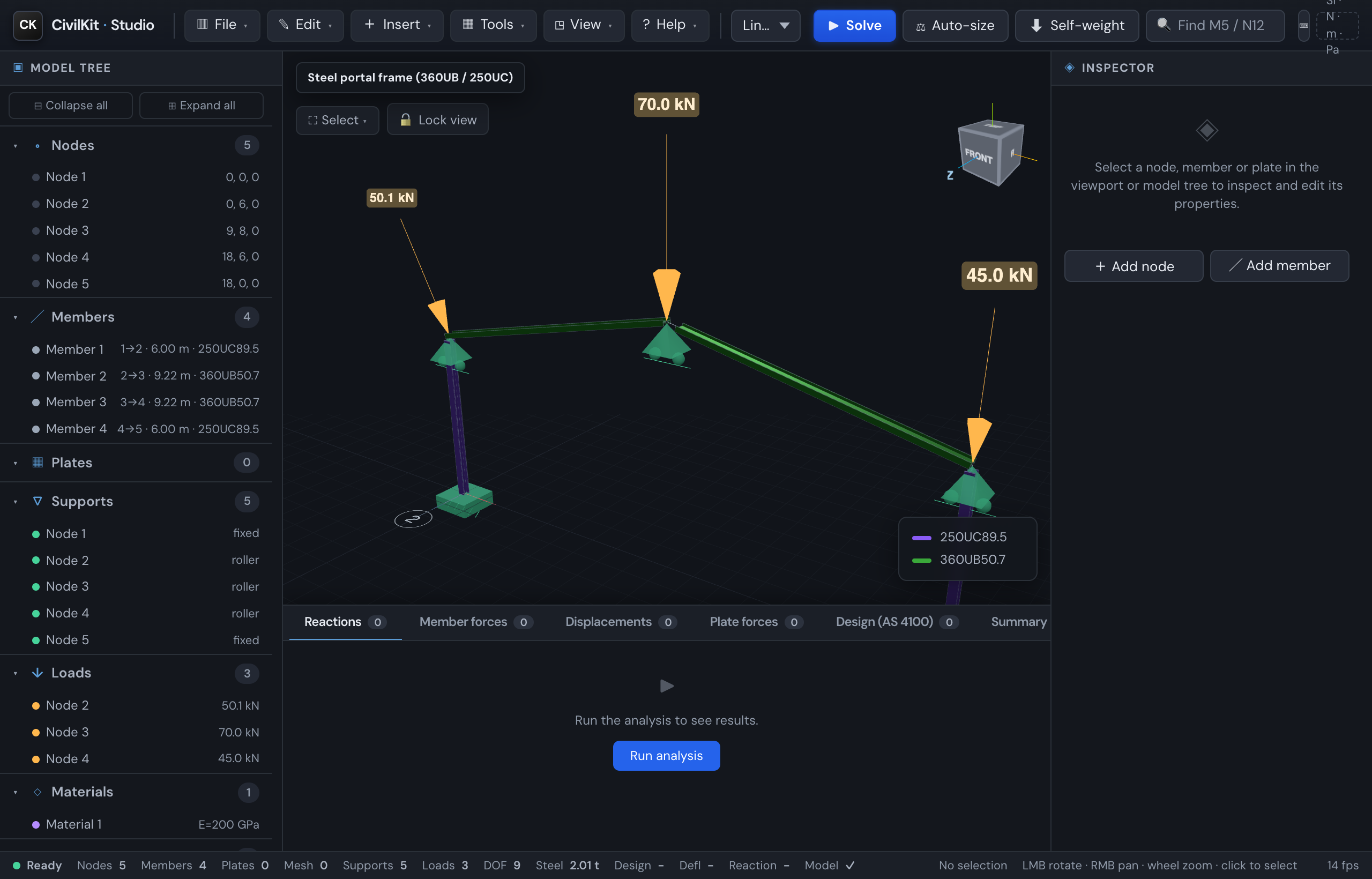
CivilKit Studio applies loads per load case, then lets you combine them (see Load combinations). All load components are in global directions - X, Y (vertical), Z - in newtons.
Nodal loads
Select a node; in the inspector set Fx / Fy / Fz (forces, N) for the active load case. Gravity is global −Y. Nodal loads draw as orange arrows in the 3D view and appear under Loads in the model tree.
Member loads
Select a member; the inspector's Member loads section lists its loads and lets you add, edit and delete them. Each load has a type, a load case, and global qx / qy / qz:
| Type | Meaning | Extra fields |
|---|---|---|
| UDL | Uniformly distributed load (N/m) over the whole member | - |
| Point | Concentrated force (N) at a position | position 0-1 along the member |
| Trapezoidal | Linearly varying load (N/m) | end intensities q2 + start/end span 0-1 |
Use + UDL or + Point load to add one; the 🗑 button deletes it. Member loads draw as a row of orange arrows along the loaded span (one arrow at a point load's position) and are listed in the model tree.
Self-weight
Click ⬇ Self-weight in the toolbar (or press W) to add each member's dead load automatically - a gravity UDL of mass/m × 9.81 in −Y, computed from the assigned catalogue section. Click again to remove it. Self-weight UDLs are managed by the toggle (shown muted grey in 3D) and are not listed in the member-load editor.
Checking it
After solving, the Summary tab shows an equilibrium check: the total applied vertical load (nodal + member UDL + plate pressure, factored per term for combinations) against the sum of reactions. A balanced model reads OK.
Springs & settlements
Select a node to set, per DOF (Tx Ty Tz Rx Ry Rz):
- Elastic support stiffness - a spring (kN/m for translations, kN·m/° for rotations). Works on a free DOF (elastic foundation) or alongside a restraint. The spring force appears in the node's reaction.
- Prescribed settlement - an imposed displacement (mm / mrad) on a restrained DOF, e.g. a support that sinks 10 mm. Free DOFs ignore it.
Both feed the solver directly (P9). After solving, the node's displacement and reaction reflect the spring/settlement.
Design criteria
The actions a job is designed for start from one set of design criteria on the project, agreed with the client before analysis (AS/NZS 1170.0 Cl 2.2): the importance level, the design working life, the wind region and terrain category, the seismic site (location or hazard factor Z, sub-soil class, structural system, kt) and the occupancy. They live in the report's title block (open the report page and edit the Design criteria panel) and are saved with the model.
From importance level and design life the panel derives the annual probability of exceedance for wind, snow and earthquake (AS/NZS 1170.0 Appendix F, Table F2) and shows it read-only. The Wind loads calculator and the Load generator prefill their region, terrain, probability and seismic fields from these criteria, and CivilKit.windLoads() / seismicLoads() read the same object, so the actions across a job come from one agreed set of inputs. Every field in the calculators stays editable for a one-off check.
Wind regions follow AS/NZS 1170.2:2021 Figure 3.1 (A, B1, B2, C, D and NZ1/NZ2, NZ3, NZ4); the New Zealand regions stay distinct through every generator.
Load cases
File → Load cases… lets you create, rename and delete load cases - name them G, Q, W etc. so you can apply loads per case and then combine them. The active case (the one new loads are added to, and whose results you view) is chosen in the results-panel selector. Deleting a case also removes its loads and drops it from any combination. Every model keeps at least one load case.