Appearance
Structure templates & quantities
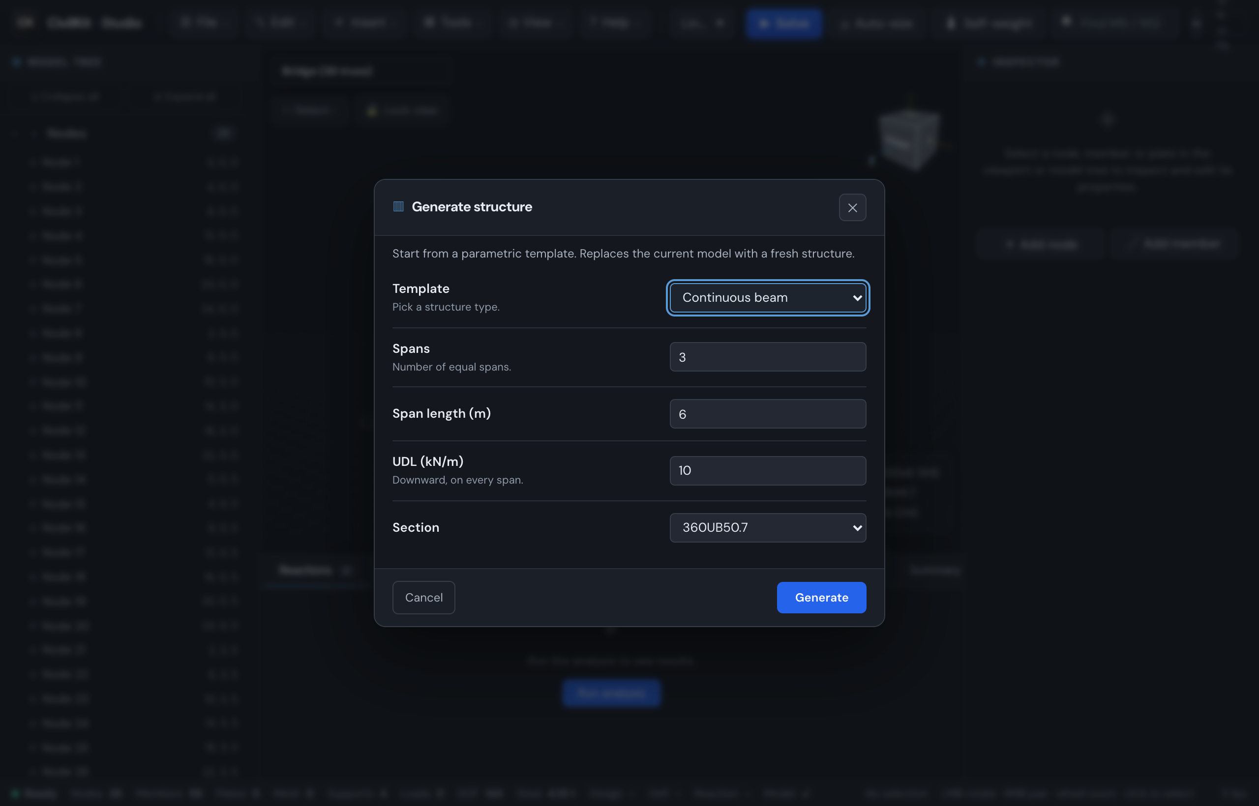
Most models do not start from a blank canvas - they start from a beam or a frame. CivilKit Studio can generate a parametric structure for you, and gives you a live steel take-off so you can see quantities from the moment you start.
Generate a structure
Open File ▸ Generate structure (or press Ctrl/⌘+K and type "generate"). Pick a template, set the dimensions, and press Enter (or click Generate). It replaces the current model with a fresh, ready-to-solve structure - real catalogue sections included.
Continuous beam
| Field | Meaning |
|---|---|
| Spans | Number of equal spans |
| Span length (m) | Length of each span |
| UDL (kN/m) | Downward uniform load applied to every span |
| Section | Catalogue section (grouped by family) |
A pin at the first support and rollers at the rest, with the rotations continuous over the supports. One span gives a simply supported beam.
Portal frame (multi-bay)
The portal builder makes a complete, solve-ready industrial shed - the bread-and-butter of Australian steel. It starts as a single gable frame and grows into a full 3D building.
| Field | Meaning |
|---|---|
| Span (m) | Eaves-to-eaves width |
| Eaves height (m) | Column height |
| Roof pitch (°) | Apex rise = (span / 2) · tan(pitch) |
| Mono-pitch | Skillion: a single-slope roof (low eave to high eave), no ridge |
| Rafter UDL (kN/m) | Gravity dead load along the rafters |
| Column / Rafter section | Chosen independently |
| Base fixity | Pinned (typical) or fixed |
| Bays | Extra frames repeated along the building length (0 = a single frame) |
| Bay spacing (m) | Frame-to-frame distance when bays ≥ 1 |
| Eave/ridge tie section | The longitudinal members tying the frames together |
| Self-weight | Adds member self-weight to the Gravity case |
With bays ≥ 1 the transverse frame is repeated every bay spacing metres and the frames are tied at both eaves and the ridge - a real 3D skeleton that solves, designs and takes off like any other model.
Advanced: haunches, knee braces & wind
The Advanced panel adds the details that make a shed a shed:
| Field | Meaning |
|---|---|
| Eave haunches | Deepens the rafter near each eave (a stepped prismatic haunch - see note), modelled as a cutting of the rafter section |
| Haunch length (m) | How far the haunch runs from the eave. 0 = auto (span/10) - the universal rule of thumb |
| Haunch depth (mm) | Total section depth at the eave. 0 = auto (2× rafter depth) - the universal rule of thumb |
| Knee braces | A diagonal brace from the column up to the rafter near each eave |
| Knee drop / run (m) | Where the brace meets the column (below the eave) and the rafter (down-slope) |
| Wind (kPa) | 0 = none. Above 0 emits indicative AS/NZS 1170 G / Q / Wu load cases plus the standard strength combinations |
| Purlin / girt spacing (m) | 0 = none. Sets the rafter/column minor-axis effective length (k_e,y) from the restraint spacing |
Haunches are stepped, wind is a scaffold
CivilKit models a haunch as a short, deeper prismatic segment (the solver has no tapered members), not a true taper - a sound, slightly conservative approximation. The Wind option is a crude uniform scaffold (roof uplift + a lateral push at the windward eave from a single pressure) to get you started with real load combinations - it is not an AS/NZS 1170.2 wind engine. Replace it with a proper wind assessment before relying on the result.
Purlins/girts set minor-axis le only
Purlin/girt spacing sets the minor-axis effective length (k_e,y) of the rafters and columns - the standard hand assumption for members restrained by secondary steel. It deliberately does not reduce the lateral-torsional buckling length, which stays at the full member (conservative): top-flange purlins only brace the compression flange under gravity, and under wind uplift you need fly braces to the bottom flange. To claim the LTB benefit, set the member's flange restrained option after checking the bracing - the full restraint schedule (per-segment, per-load-case) is a planned enhancement.
Sections are real
The section pickers list the live catalogue grouped by family (Universal Beam, Universal Column, PFC, RHS, ...). Generated members carry full geometry, so the AS 4100 design checks and Auto-size work on them immediately - and when wind is enabled the frame design-checks against the load combinations via the envelope.
Truss (parallel chord)
A parallel-chord truss with a pin + roller at the bottom-chord ends and the top-chord load carried at the panel points.
| Field | Meaning |
|---|---|
| Span (m) | End to end |
| Depth (m) | Chord-to-chord depth |
| Panels | Number of bays along the span |
| Diagonals | Pratt or Warren diagonal pattern |
| Top-chord UDL (kN/m) | Gravity load along the top chord |
| Section | One section for the whole truss |
Building frame (multi-storey)
A regular multi-bay, multi-storey moment frame - columns and floor beams on a grid.
| Field | Meaning |
|---|---|
| Bays / Storeys | Grid divisions across and up |
| Bay width / Storey height (m) | Grid spacing |
| Floor UDL (kN/m) | Gravity load on the floor beams |
| Base fixity | Fixed (typical) or pinned |
| Column / Beam section | Chosen independently |
Floor grid / grillage
A flat horizontal grid of intersecting beams in the X-Z plane, edge-supported, with a uniform pressure carried down on every beam.
| Field | Meaning |
|---|---|
| Bays X / Bays Z | Grid divisions in each direction |
| Spacing X / Z (m) | Grid spacing |
| UDL (kN/m) | Gravity load on all beams |
Arch (parabolic)
A parabolic arch discretised into straight segments, pinned (or fixed) at the springings.
| Field | Meaning |
|---|---|
| Span (m) | Springing to springing |
| Rise (m) | Height at the crown |
| Segments | Number of straight members along the arch |
| UDL (kN/m) | Gravity load along the arch |
| Springings | Pinned or fixed |
Lattice tower
A square four-leg lattice mast - legs, a tie ring at every level, and an X-brace on each face per panel, fixed at the base.
| Field | Meaning |
|---|---|
| Height (m) | Base to top |
| Panels | Levels up the height |
| Width (m) | Square plan width |
| Lateral UDL (kN/m) | Optional wind load on the legs (0 = none) |
Dome (ribbed)
A ribbed hemispherical dome - meridional ribs and horizontal rings meeting at a single apex, fixed at the base ring.
| Field | Meaning |
|---|---|
| Radius (m) | Hemisphere radius |
| Rings | Horizontal rings from base to apex |
| Segments | Nodes around each ring |
| Rib UDL (kN/m) | Gravity load along the ribs |
Live steel take-off
Before you even solve, the Summary tab shows a Model overview: node / member / plate / support / load-case counts plus a steel take-off grouped by section - count, total length, mass per metre, and total mass, with a grand-total tonnage. It recomputes as you re-size members, so you can watch the tonnage change while you optimise. Copy it straight to a spreadsheet with Copy (TSV).
If any member sits on a section with no catalogue mass (e.g. a generic section not yet assigned a profile), it is excluded from the tonnage and the total notes how many members were left out - so a take-off is never silently partial. The same take-off and note appear in the PDF report.
Go to an element
In large models, press Ctrl/⌘+K and type an element id - n47, m12, or a bare 47 - to select and frame that node or member in the 3D view.