Appearance
Concrete slab on pad footings
A worked example: a 16 x 8 m suspended concrete slab carried on fifteen pad footings at a 4 m grid, from geometry through to a reinforcement drawing and bar schedule.
The numbers quoted throughout are the ones this model actually produces, so you can check your own run against them.
What you are building
| Slab | 16 x 8 m, 200 mm thick, meshed at 1.0 m |
| Concrete | N32 (f'c = 32 MPa), E = 30 GPa |
| Footings | 15 pads at a 4 x 4 m grid, 1.2 x 1.2 x 0.4 m, on 400 x 400 piers 0.6 m deep |
| Reinforcement | N12 at 275 crs, both directions, both faces |
1. Start a blank model
File ▸ New model (shortcut N) opens the Generate structure dialog. Its templates are all steel frames and trusses, so choose Start blank at the bottom left.
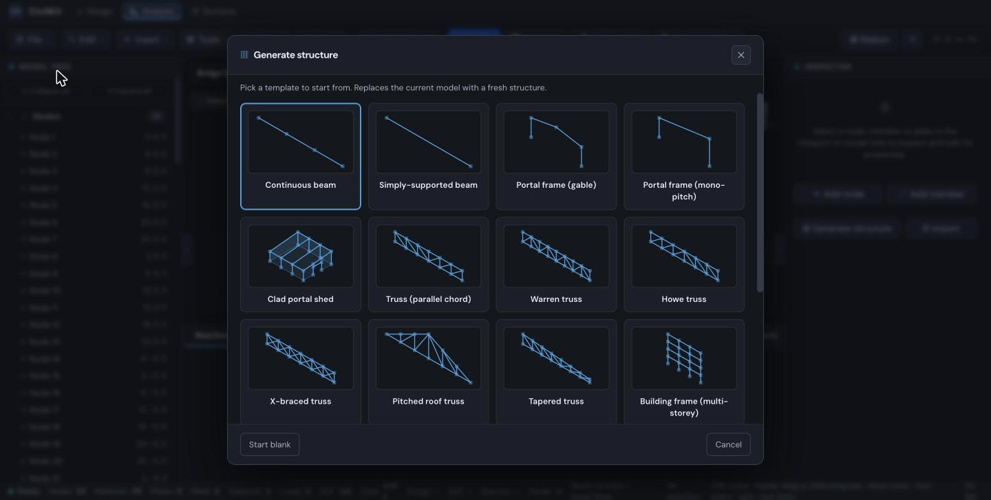
There is no slab template yet
Every template in this dialog is a steel frame. A parametric concrete-slab template is a known gap; until it lands, build the slab with the script in step 2.
2. Build the slab and footings
The fastest reliable route today is the console API. Open the browser console on the Studio page and run the following. It builds the slab mesh, the pad footings, and the slab self-weight as nodal loads, then solves.
js
const f = window.__fem, G = 9.80665, RHO = 2400;
const LX = 16, LY = 8, MESH = 1.0, T = 0.20;      // slab
const PAD = 1.2, T_PAD = 0.40, PIER = 0.6;         // footings
const GX = [0, 4, 8, 12, 16], GY = [0, 4, 8];      // footing grid

const nodes = [], plates = [], members = [], nodal_loads = [];
let nid = 0, pid = 0, mid = 0, lid = 0;
const N = (x, y, z, r = 0) => {
  nodes.push({ id: ++nid, x, y, z, restraint_flags: r });
  return nid;
};

// Slab mesh at z = 0
const nx = LX / MESH, ny = LY / MESH, S = [];
for (let j = 0; j <= ny; j++) {
  S[j] = [];
  for (let i = 0; i <= nx; i++) S[j][i] = N(i * MESH, j * MESH, 0);
}
for (let j = 0; j < ny; j++) for (let i = 0; i < nx; i++)
  plates.push({ id: ++pid, node_ids: [S[j][i], S[j][i + 1], S[j + 1][i + 1], S[j + 1][i]],
                material_id: 1, thickness: T });

// Slab self-weight, by tributary area
for (let j = 0; j <= ny; j++) for (let i = 0; i <= nx; i++) {
  const A = (i === 0 || i === nx ? 0.5 : 1) * (j === 0 || j === ny ? 0.5 : 1) * MESH * MESH;
  nodal_loads.push({ id: ++lid, node_id: S[j][i], load_case_id: 1,
                     fx: 0, fy: 0, fz: -A * T * RHO * G, mx: 0, my: 0, mz: 0 });
}

// Pad footings: a pier down to a pad bearing on soil
const h = PAD / 2;
for (const gx of GX) for (const gy of GY) {
  const top = S[gy / MESH][gx / MESH], P = [];
  for (let j = 0; j < 3; j++) {
    P[j] = [];
    // Tz at every pad node is soil bearing; the centre node is pinned so the pad cannot slide
    for (let i = 0; i < 3; i++) P[j][i] = N(gx + (i - 1) * h, gy + (j - 1) * h, -PIER,
                                            (i === 1 && j === 1) ? 7 : 4);
  }
  for (let j = 0; j < 2; j++) for (let i = 0; i < 2; i++)
    plates.push({ id: ++pid, node_ids: [P[j][i], P[j][i + 1], P[j + 1][i + 1], P[j + 1][i]],
                  material_id: 1, thickness: T_PAD });
  members.push({ id: ++mid, node_a: top, node_b: P[1][1],
                 material_id: 1, section_id: 1, member_type: 0, beta: 0 });
}

f.loadModel({
  schemaVersion: 2,                                 // see the warning below
  name: '16 x 8 m concrete slab on pad footings',
  nodes, members, plates, nodal_loads, member_loads: [],
  materials: [{ id: 1, e: 30e9, g: 12.5e9, density: 2400 }],
  sections: [{ id: 1, a: 0.16, iyy: 2.1333e-3, izz: 2.1333e-3, j: 3.60e-3 }],
  load_cases: [{ id: 1, name: 'G - dead' }],
});
Always set schemaVersion: 2
Studio is Z-up: Z is the vertical axis. A model loaded without schemaVersion is treated as a legacy Y-up file and migrated, which swaps Y and Z and tips your slab on edge into a vertical wall. If your slab comes in standing up, this is why.
Press Solve. You should get 288 nodes, 188 plates, 15 members and 135 supports.
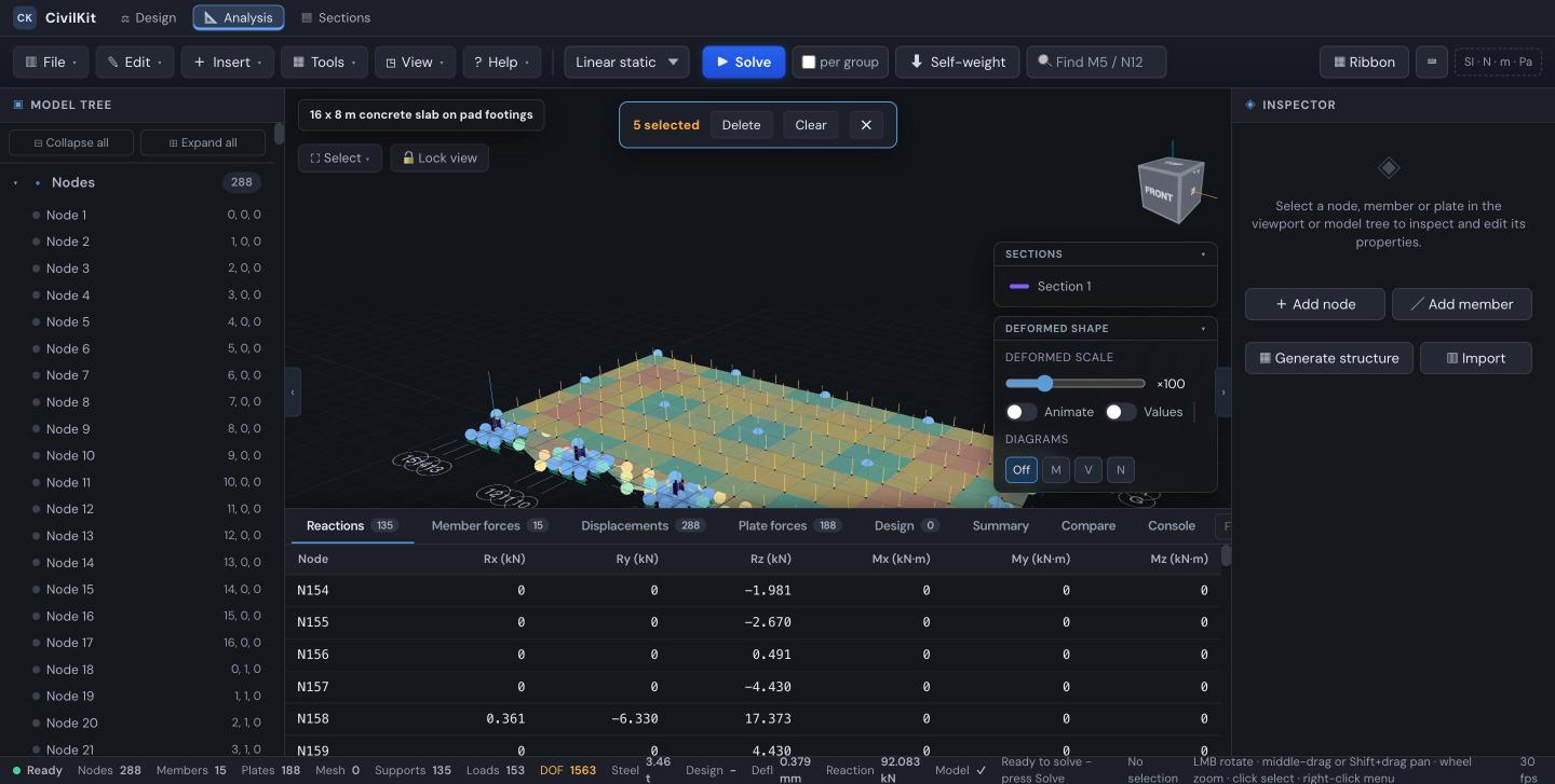
3. Check that it adds up
Before trusting any result, check equilibrium. In the console:
js
const lc = window.__fem.State.results.load_cases[0];
const applied = window.__fem.State.model.nodal_loads.reduce((s, l) => s + l.fz, 0) / 1000;
const reacted = lc.reactions.reduce((a, b) => a + (b.rz || 0), 0) / 1000;
console.log(applied.toFixed(1), 'kN applied |', reacted.toFixed(1), 'kN reacted');
Applied and reacted should agree to the last digit. For this model: 602.5 kN of slab self-weight, plus 33.9 kN of pier self-weight if self-weight is enabled, giving 636.4 kN each way.
Count every load before calling it an error
If the sums disagree, check what you are counting before suspecting the solver. Pier self-weight is applied as member UDLs and is easy to leave out of the "applied" side of your own check.
Maximum deflection is 0.38 mm, and the reactions table shows real values at each of the fifteen pads rather than zeros.
4. Reinforcement
The solver produces four Wood-Armer design moments per plate (mx_star_bottom, my_star_bottom, mx_star_top, my_star_top), which are the moments the reinforcement in each direction and face must carry. @civilkit/core/rebar turns them into bars.
js
import { slabRules } from '@civilkit/core/as3600_detailing';
import { slabReinforcement } from '@civilkit/core/rebar';

const rules = slabRules({
  thickness: 0.20, d: 0.164, fc: 32e6, fSy: 500e6,
  exposure: 'A1',              // interior residential, AS 3600 Table 4.3 Item 2(a)(i)
  support: 'columns',          // supported on pads at grid points, Cl 9.1.1(a)
  castAgainstGround: 'membrane', // Cl 4.10.3.5(a): +10 mm
});

const layers = slabReinforcement({
  moments: { mxBottom: 8810, myBottom: 8570, mxTop: 11480, myTop: 11190 },  // N.m/m
  thickness: 0.20, coverBottom: rules.cover, coverTop: rules.cover,
  fPrimeC: 32e6, fSy: 500e6, rules,
});
For this slab that gives:
| Cover | Max spacing | Minimum steel | |
|---|---|---|---|
| Value | 30 mm | 300 mm | 397 mm²/m |
| Source | Table 4.10.3.2 + Cl 4.10.3.5(a) | Cl 9.5.1(b), lesser of 2.0 Ds or 300 | Cl 9.1.1(a) |
| Layer | M* (kN·m/m) | d (mm) | As design | As required | Bars | As provided |
|---|---|---|---|---|---|---|
| Bottom X | 8.81 | 164 | 127 | 397 | N12 @ 275 | 411 |
| Bottom Y | 8.57 | 152 | 134 | 397 | N12 @ 275 | 411 |
| Top X | 11.48 | 164 | 166 | 397 | N12 @ 275 | 411 |
| Top Y | 11.19 | 152 | 175 | 397 | N12 @ 275 | 411 |
Two things worth reading off that table:
- Minimum steel governs every layer. The moments only need 127 to 175 mm²/m; Cl 9.1.1 requires 397. That is normal for a lightly loaded slab, and the layers are flagged
governedByMinimumso the calc sheet can say so rather than implying the bars were sized by moment. - The two directions have different effective depths. Bottom X gets d = 164 mm and bottom Y gets 152 mm, because the two orthogonal layers cannot occupy the same depth: the inner layer sits one bar diameter further in. Treating both as 164 would overstate the Y direction.
Cover is not guessed
requiredCover reads AS 3600 Table 4.10.3.2 and refuses rather than inventing a value:
- An em dash in the table means that strength is not permitted for that exposure, and you get an error naming the combination, not a number.
- A bracketed figure needs the Clause 4.3.2 concession, so it is only returned when you opt in.
- Cover from this function is durability only. Clause 4.10.1 requires the greatest of durability, aggressive or saline ground (Tables 4.8.1 and 4.8.2, not implemented) and fire (Section 5). Every result carries that caveat.
5. Drawings and bar schedule
@civilkit/detailing produces the plan, section, footing detail and schedule:
js
import { slabRebarPlanSVG, slabSectionSVG, padFootingRebarSVG,
         barScheduleRows, barScheduleHtml, barScheduleCsv } from '@civilkit/detailing/rebardraw';

const plan = slabRebarPlanSVG({
  lengthX: 16, lengthY: 8,
  xLayer: layers.bottomX.bars, yLayer: layers.bottomY.bars,
  cover: rules.cover, face: 'bottom',
});
Bars are drawn at their true spacing rather than schematically, so a wrong spacing looks wrong.
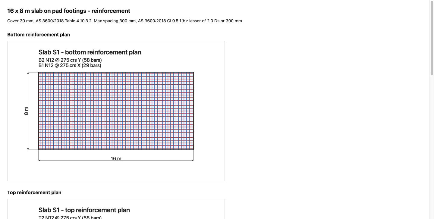
The schedule merges identical marks and totals length and mass:
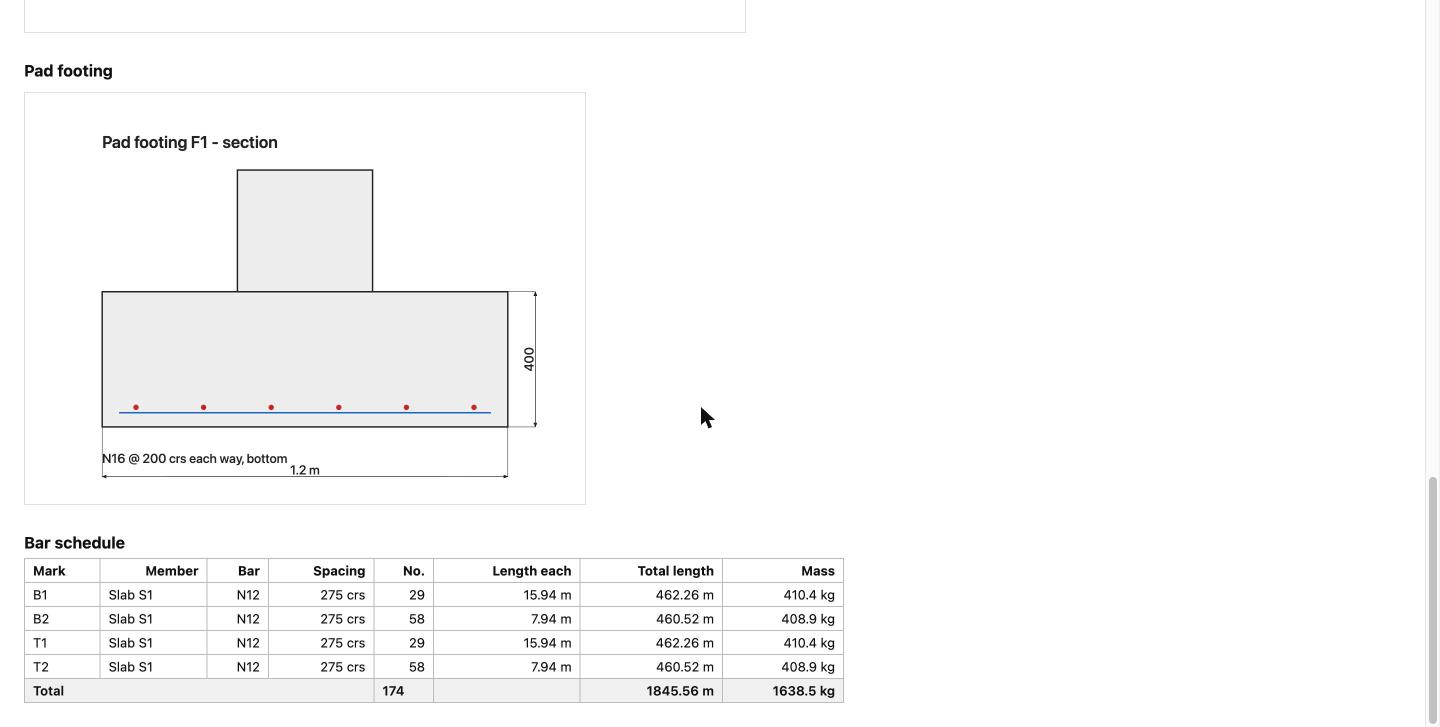
For this slab: 174 bars, 1845.6 m, 1638.5 kg.
Mesh density
The slab above is meshed at 1.0 m, giving 16 x 8 elements. Refining the mesh refines the moments; the plate element converges to the Timoshenko solution from below, so a coarse mesh reads slightly stiff. If you need accurate hogging moments over the pads, refine locally around them.
Historical note
Builds before July 2026 had a plate element that admitted a spurious zero-energy mode, which made results sensitive to whether the mesh division counts were odd or even and could give displacements of ~10¹⁰ mm. That element was replaced with a MITC4 assumed-strain formulation. If you are on an older build and see an implausible deflection or reactions that do not balance the load, update.
What is not covered yet
- No slab or footing template in the Generate structure dialog.
- Reinforcement is not yet stored on the model, so it does not persist with the file.
- Cover for aggressive or saline soils (Tables 4.8.1, 4.8.2) and fire (Section 5) is flagged, not computed.
- The bar schedule gives lengths, not bending shapes or laps, so it is not yet a bar-bending schedule.
- Punching shear at the pads is available in the pad footing calculator but is not applied automatically from this model.